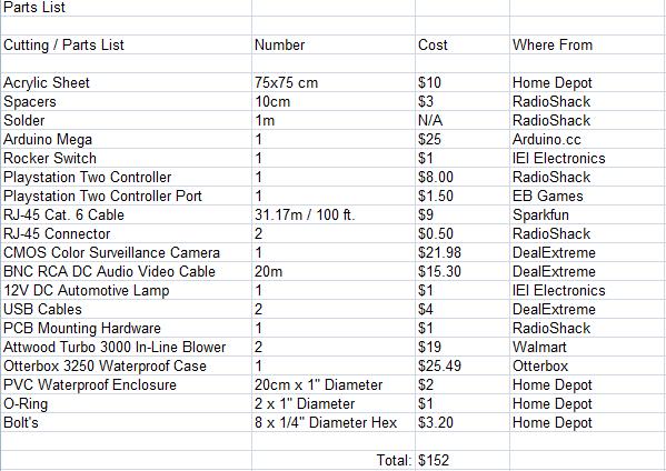
The construction of the controller box is a very intricate process that requires focus and attention to details throughout the processing and assembly phase. The Materials processing phase consists of preparation and alteration of any materials throughout the construction of the controller box. The main component of the controller box that has to be altered is the acrylic project box. The rest of the components are materials, but they are already assembled, they just need to be installed into the median (acrylic.)
Below is a document known as a “Plan of Procedure” which is a detailed list of orders and instructions regarding the altering and assembly of any type of materials, parts, pieces included within the design. The objective of this plan of procedure is to build and assemble the controller box for the Underwater Remote Operated Vehicle
Material Processing
*Note: All Tools being used are on the Construction Phase Partition
1. Use templates included and adhere to the acrylic via temporary methods
2. Using the Band saw (T2), cut out the portion along the exterior lines on the template, of the acrylic.
3. Using the Drill press, T1, use hole saw drill bit, T6, on the acrylic surface, and make holes for the different components on each face of the acrylic
4. All dimensions in drill bit sizes (in United States Standard Sizes) are included on the template.
5. Repeat steps 1-4 for all 6 faces of the controller box.
6. Using a dremel and or sandpaper, S3, file down the rough edge surfaces that were drilled out
7. Ensure all components will snugly fit accurately with the smoothened edges.
8. Ensure all parts fit in accurately and correctly before continuing
9. Drill out the holes for the mounting materials for the Circuit board on the median
10. While the bottom is separated from the assembly, solder or attach any additional wires and test the circuit before permanent assembly.
11. Check the pieces next to others for accurate fit before moving onto Assembly Procedures.
Assembly Procedure
1. Install pieces into corresponding places onto each face of the controller box.
2. Use epoxy to bind the materials into place for solid professional installation.
3. Adjust the parts as needed within the 15-30 minute (depending on the epoxy) period and then allow a 24 hour drying period for the epoxy to crystallize.
4. Solder wires to any ports or components being installed in the walls or bottom of the acrylic before continuing including mounting brackets / posts.
5. Epoxy the wall of the acrylic to the bottom along the edge and to ensure a 90 degree angle, work against a regimented 90 degree surface (Right angle edge.)
6. Install the other 3 walls around the area of the box and ensure all edges are correct. Use spreaders and vices to ensure the edges are flush.
7. Use the mounting screws and drill out inserts for the screws to be tightened into a solid position for a solid and sturdy construction.
8. Reinstall any removed components and tighten any screws of materials on the mounting brackets installed during step 4.
9. Take top face of the controller box and install the hinges onto the acrylic.
10. Repeat step 3 for the top face of the controller box with all components.
11. Allow the 24 hour drying period to occur before altering the acrylic any further.
12. Install the hinges into the pre-drilled corresponding part on the top face.
13. Install the top face onto the rest of the project box.
14. Check for any imperfections during the installation and correct them as needed.
15. Install the rubber feet onto the bottom of the project box and open the top face to tighten the screws of the rubber feet and all components to ensure the protection of the project box and to finalize the product


