Marking Period 1:
Contact #1
Contact Submission Type: Documented Video Conference with Mentor
Point Credit / Value: 2 Points
Contact Name: Wynston Chew
Date: Thursday, September 22, 2011
Time: 7:20 PM EST (9:20 AM Australian Time)
Reference / Objective: Determine how to find the purpose of each pin on the Playstation 2 Controller and other devices.
Questions: The Playstation Two controller has default wires or pins for the connecting port in order to function. Considering that I do not know their purpose, I need to figure out a way to determine their use on the controller. Worst case scenario is that I can take the controller apart and I can re-wire the outgoing pins to my own contacts and make each button merely a push-button switch.
Discussion: Through the Video Conference that my mentor and I organized, I got to take a look at his personal workstation and he displayed how he would tackle such a situation. It took him a few seconds to determine what type of equipment he would need and a few seconds to search the internet for the type of controller, but after determining what type of settings he needed, he setup his equipment and performed the difficult task at hand. Part of the difficulty that I had with accomplishing the task he performed was due to the fact I didn’t have the equipment that he does (which is very expensive) and if I did obtain the equipment at a cheaper rate, it would not be very accurate and could lead to problems in the future.
Answers / Conclusion: To figure out the purpose of an existing controller, you can use the probes of an oscilloscope to determine their serial data. Using this information, I can later program the microcontroller to use this serial input data as an “input” command for my computer to manipulate. Because the values are more precise using expensive equipment, the microcontroller will most likely have ease in finding the controller and have high response time transmitting at a very close “native” spectrum.
Pictures from the Video Conference / Discussion:


Contact #2
Contact Submission Type: Documented Video Conference with Mentor
Point Credit / Value: 2 Points
Contact Name: Wynston Chew
Date: Friday, September 30, 2011
Time: 8:15 PM EST (10:15 AM Australian Time)
Reference / Objective: Understanding the concept of two potential alternate solutions by figuring out the process of determining the function of switches and labeling them by type and use.
Questions: Switches are used universally in order to manipulate things where current has to be alternated in a specific way. People have used switches to control motors, how can I optimize switches and motor use as opposed to using 2 for each axis of moment (6 total) and having 2 wires each for current (12 wires). Minimization on these key focus points will optimize the ROV’s efficiency and maximize its functionality and practicality. This is a difficult task at hand, and determining it would significantly advance me in the design process.
Discussion: Through the Video Conference that my mentor and I organized, he had a strong background in switches and their application. He had to use a lot of them for his award-winning Self Balancing robot. He displayed to me the use of a few switches on his robot. He gave me an example of an SPST (Single Pole, Single Throw) switch. In his case, his functioned in an on-off function which means it only has two positions. He showed me an example of an SPST switch that had 3 positions, up, middle, and down. This is used to have two connections sharing one common wire in the center but can stay in the central (off) position when it is connected to nothing. He explained what a DPDT (Double Pole, Double Throw) switch is as well. This is similar to an SPST in function being either 2 positions or 3 positions, but this has 2 contacts which connect 2 common wires central wires to two separate connections. This can be used to alternate polarity of a motor or alternate the current of outgoing wires.
Answers / Conclusion: This is definitely a viable solution to the task at hand that is within our specs and limits. Through his explanations of the switches, I figured out a way to minimize wires and to maximize performance and utilization of the motors. I can run the motors clockwise and counterclockwise using a Double Pole, Double Throw Switch. I can put the motor wires on the central two and alternate the polarity on the ends of the switch in order to oppose the initial direction. Or, I can put the current-bearing wires on the central two poles and alternate the polarity of the motors on the end of the switch to oppose initial direction. Both of these are viable and will minimize my wire / tether weight. This is definitely something to consider because it’s a working solution.
Pictures from the Video Conference / Discussion


Contact #3
Contact Submission Type: Documented Video Conference with Mentor
Point Credit / Value: 2 Points
Contact Name: Wynston Chew
Date: Thursday, October 13, 2011
Time: 6:00 PM EST (8:00 AM Australian Time)
Reference / Objective: Figure out the Arduino Interface; understand his expertise through his previous projects, Successfully Code my Arduino to my Rationale Specs. Figure out how to mount a difficult device such as the Arduino.
Questions: How do I use the Arduino Interface? How much knowledge does he have with Arduino Devices, How can I code my Arduino to meet the specs and be within the limits of my project scope? How can I mount this type of Printed Circuit Board on my project box I am creating?
Discussion: Through the Video Conference that my mentor and I organized, we began discussing his capstone project that he had to complete. His was creating a Self-Balancing Robot using an Arduino Microcontroller. He was the same age as me when he conducted the project on his own and he began learning how to program the microcontroller through intensive books which he recommended. Following his recommendations, he offered me some advice as to where I should start in practice and what type of guidelines I should follow in order to meet my goal. Following this, we created a sample code that I used on my Arduino board and it was very successful and motivated me to continue and feel more confident with Alternate Solution #3. Lastly, I asked how I could mount a PCB (printed circuit board) such as this one due to its unique shape. He encountered the same problem with his and he showed me how he manipulated the o-ring’s that he purchased from a local hardware store in order to accomplish this task.
Answers / Conclusion: I have concluded from this conversation that I have a path of study that I must conduct with understanding Arduino Language in order to complete this project. In addition, I’m going to need to make some additions to my Arduino in order for it to perform in the way I desire it to function. Hopefully using my coding background and my will to learn it as well as his knowledge behind Arduino, I plan on following through with this idea and it should follow through as the Alternate Solution suggests. Lastly, I learned how to mount an Arduino Microcontroller like this to an acrylic sheet similar to how he did his project. This will definitely help me in accomplishing my challenge / task at hand.
Pictures from the Video Conference / Discussion:


Contact #4
Pictures from the Video Conference / Discussion:


Answers / Conclusion: He told us that our design might be a bit overbearing but could be corrected easily. He said that the structure might be a bit too buoyant, but we can add weight or chop out pieces of PVC to correct the problem 3rd marking period. He said that the waterproof quality was immaculate on the design and our apparatus to hook up equipment was more than sufficient. Lastly, he commented on the superiority of our design in the electronics component. Our electric devices are very powerful and capable of doing a lot of tasks simultaneously and efficiently. He commended us on our design as a group, and our individual efforts. He told us that our center of buoyancy and mass is relatively sound because they are vertically and horizontally oriented at this time. He offered us many solutions to minimize and maximize weight to perform better and he didn’t foresee any problems in the future for us.

Pictures from the Video Conference / Discussion:


Contact Submission Type: Documented Video Conference with Mentor
Point Credit / Value: 2 Points
Contact Name: Wynston Chew
Date: Monday, October 17, 2011
Time: 6:30 PM EST (8:30 AM Australian Time)
Reference / Objective: Determine how to measure cylindrical objects technically. Figure out how to create professional appropriate size holes in the acrylic for the foundation of the control box to install components.
Questions: How can I measure cylindrical switches without struggle? How can I create the professionally positioned snug sized hole for the component?
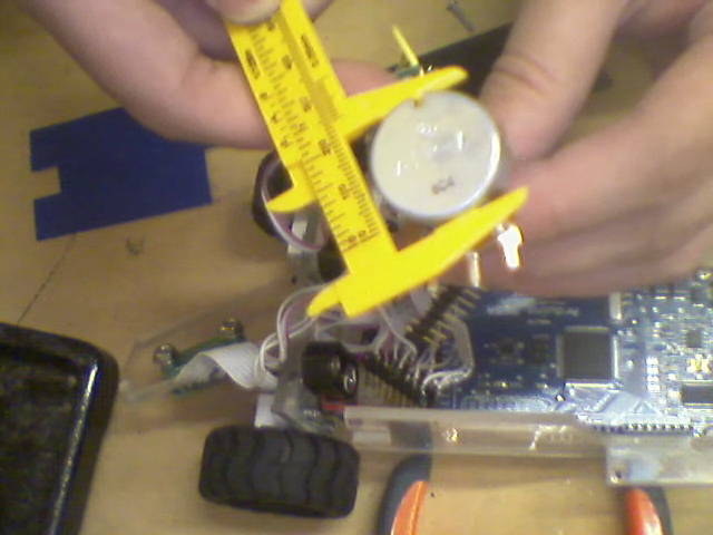
Discussion: He told me that using a caliper, preferably a digital one will give me accurate measurements as far as diameter for smaller components. Once I know the size in centimeters, millimeters, inches or whatever unit the digital caliper displays, I should convert them to drill bit sizes. To ensure that they are consistent throughout, measure the drill bit and the component and always round downward with the decimals. He said I could always use a dremel with a sanding bit and go up, but it’s hard to put the material back on, jokingly. He showed me that for his cylindrical motors and cylindrical switches, you generally have to install them in two steps. First of which is to unscrew a default ring that comes with the component, and then install the switch topside first. This gives the switch the professional looking molding around the edge that looks flush and installed properly with the surface. This creates a great appeal in construction. Then you take the washer with threads on it and install it on the underside of the control box and twist tightly over the threads. Once installed correctly, and properly, and it has the correct circular orientation, then he prefers to epoxy them into position so they don’t move and the installation is permanent and professionally performed. From the underside of the components, you can solder the wires and route them using O-Rings or other Wire-organizing devices to a common hinge point. This will allow for quick servicing and optimal for presentations.
Answers / Conclusion: He definitely made reassuring comments and gave very helpful advice as to how he has learned to create and install components in project boxes over the years. Some of the things that he mentioned I wouldn’t have even thought about until he mentioned them. I feel like I’m going to perform better than average with some assist from Wynston’s advice, but because this is my first installation and creation of a project box, it may be sloppy being that it’s my first job. Hopefully with his suggestions, everything will work above expectations and be proficient enough for operations and to meet my group’s needs.
Pictures from the Video Conference / Discussion:


Contact #5
Contact Submission Type: Documented Video Conference with Mentor
Point Credit / Value: 2 Points
Contact Name: Wynston Chew
Date: Saturday, October 29, 2011
Time: 7:15 PM EST (9:15 AM Australian Time)
Reference / Objective: Measure and figure out how to read the bands on resistors. Use tools to figure out values and use physics to determine their use in the circuit.
Questions: How can I measure resistance and capacitance on components that I may need to add in order to maintain the 5V Logic across the Playstation Two controller?
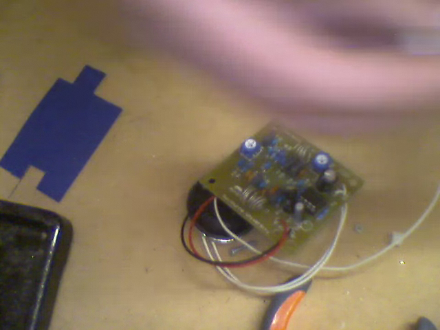
Discussion: Wynston taught me the old fashioned way of determining values. Using a resistance chart, you are able to take the bands of color and determine impedance, resistance values as they multiply across. These values are significant to determining how much resistance the component as a whole could hold back. For my project, one of my pins is running a bit over 5V Logic and the Arduino Circuit board cannot understand it. In order to figure out what value resistor I need, I have to do some math to manipulate the numbers and find out where the error is in the circuit. After the creation of multimeters, he showed me how to use one, and what settings to place it on in order not to blow a fuse or any of the internal components and how they can determine the value of the resistor used in a previous circuit or how to find out what resistor will work with the circuit.
Answers / Conclusion: Using a multimeter, I can now figure out what value resistor I need to put onto my Arduino and my Breadboard in order to maintain the status of the 5V logic across the board. This is importance because the Arduino can not effectively communicate with the controller and receive proper information if it is not in 5V Logic. The resistance that I needed, I was able to calculate through Physics came out to be 10,000 Ohms (a Unit of resistance). After adding a 10k Ohm Resistor to my circuit board, the controller and the Arduino synced in perfection and harmony.
Pictures from the Video Conference:


Marking Period 2:
Contact #1
Contact Submission Type: Live Broadcasted Skype ™ Video Call over iPhone 4S
Point Credit / Value: 2 Points
Contact Name: Wynston Chew
Date: Wednesday, December 14, 2011
Time: 1:20 – 2:40 PM EST (5:20 - 6:40 AM Australian Time)
Reference / Objective: Introduce Wynston to the Facilities offered on campus by giving him a video tour. Show him the type of equipment we have available to the students in order to find better alternatives for completing the same task at hand. Introduce him to the instructors formally and show teachers alternative contact methods for students to utilize in the future.
Questions: How would I be able to mount the standoffs on the bottom? What type of place would have the Type M Screws I would need to buy in order to get a better mount on the hardware in the controller box?
Discussion: Through the Video Conference that my mentor and I organized ahead of time to take place Wednesday at 1:20 PM EST, I was able to give him an adequate tour of the facilities and the type of equipment we had available to students here on campus. Afterwards I showed him my current progress of where I was throughout the project and showed him the different type of points I’ve had difficulty in and the points I’ve had much success in. I noted his suggestions and his techniques that he recommended to me throughout the video call and referenced them in the future. We discussed what type of apparatus we were going to use for waterproofing the camera for better fail-proof methods. In addition, we talked about what size conversions would be most universal and would be the easiest to find in my local town or department store.
Answers / Conclusion: We concluded that the method I had down for the plan of procedures is probably fine for the type of construction I’m performing here at school for the quality I am shooting for. We also talked about the different alternatives such as cutting some pieces of the acrylic with a dremel attachment head which I was unaware of. In addition, he was very pleased with my construction and quality / professionalism throughout the project so far and he’s looking forward to seeing my progress in the future.
Contact #2
Contact Submission Type: In-Person Alumni Discussion
Point Credit / Value: 2 Points
Contact Name: Thomas Divine
Date: Thursday, December 23, 2011
Time: 1:20 PM – 2:40 PM EST
Reference / Objective: Determine an alumni student’s perspective and opinions on the projects we are working on to date. Ask questions regarding his concern that might be troubling in the future.
Questions: How do you calculate the center of mass and the center of buoyancy? How is the structure as a whole and what would his recommendations be for any problems? What type of ways can we add weight to the overall structure, and how can we minimize weight as a group? Are my electronics versatile and compatible to the equipment I am using and/or will I foresee any problems in the not-so-distance future.
Discussion: Thomas Divine was a student who came to MAST a few years ago. He is currently working on Autonomous Roving Vehicles (ARV’s.) These are robots that have sensors on board and are able to operate on their own to complete certain functions or tasks they were designed to do. He experienced some problems during his construction, but moved on and learned how to fix them through more assembly tasks and engineering classes.
Answers / Conclusion: He told us that our design might be a bit overbearing but could be corrected easily. He said that the structure might be a bit too buoyant, but we can add weight or chop out pieces of PVC to correct the problem 3rd marking period. He said that the waterproof quality was immaculate on the design and our apparatus to hook up equipment was more than sufficient. Lastly, he commented on the superiority of our design in the electronics component. Our electric devices are very powerful and capable of doing a lot of tasks simultaneously and efficiently. He commended us on our design as a group, and our individual efforts. He told us that our center of buoyancy and mass is relatively sound because they are vertically and horizontally oriented at this time. He offered us many solutions to minimize and maximize weight to perform better and he didn’t foresee any problems in the future for us.
Contact #3
Contact Submission Type: Broadcasted Skype™ Video Call
Point Credit / Value: 2 Points
Contact Name: Wynston Chew
Date: Monday, December 19, 2011
Time: 6:40 – 8:00 PM EST
Reference / Objective: Wire Management and Ribbon Cable Explanation
Questions: How would I maximize the efficiency of the use of my existing wires and minimize the amount of wires used in the total construction.
Discussion, Answers, and Conclusion: We would like to minimize our wire usage as much as possible. Wynston and I have come to the conclusion that we want to just use the 65’ tether. It consists of 6 wires. We plan on using 2 wires for the positive and negative for the camera feedback. In addition, use 2 wires for the battery connections for all of the electric on board. And finally, the last 2 wires will be for data receiving and data transmitting. These wires are going to use all the existing pieces not to damage the cable or permanently tether it to the controller box, but instead, used connectors from a circuitry shop to plug in and disconnect the wires. These 6 wires should maximize our performance and should minimize the impact of the tether on the rest of the ROV. Below is a picture of a data socket that Wynston used for his Self-Balancing Robot between the controller and the uBot (The name of his robot.)

Contact #4
Contact Submission Type: Broadcasted Conference Call over Skype™ Telecommunications network
Point Credit / Value: 2 Points
Contact Name: Wynston Chew
Contact Time: 9:00 - 10:25 PM EST
Reference: Case / Acrylic Assembly
Discussion, Answers, and Conclusions: In order to make sure the walls of the case are at right angles, he recommended using something called a right angle clamp. He said that you can bing 2 edges together using one clamp at a given time. He recommended either epoxy, but shied away from the adhesive caulk they recommended to me at the Home Depot. He stated that I should have all wire connections done and do the height of the box and then attach the bottom. This way, I maintain my right angles and everything adequately fits together. The back hinges should be drilled out before the sides are epoxied together. The hardware such as hinges with screws and bolts can be attached at a later date .We've decided that all the sides will be adhered together and then will be attached to the bottom of the project enclosure without hardware installed. Any plugs, or parts that are pound to the acrylic edges should be properly installed and epoxied into place before the walls are bound together.

Contact #5
Contact Submission Type: Broadcasted Skype™ Video Call
Point Credit / Value: 2 Points
Contact Name: Wynston Chew
Date: Monday, January 8, 2012
Time: 9:25 – 10:55 PM EST
Reference / Objective: Acrylic and Hardware Mounting
Questions: What type of washers, nuts, screws, bolts, and other pieces should I acquire to make sure that all pieces including the microcontroller are mounted adequately to the acrylic walls / faces?
Discussion, Answers, and Conclusion: Wynston has worked with ton’s of various components involving different types of mounting methods to have them work successfully. He stated that if the installation would be permanent, he recommends using a tight fit using epoxy, and a lock washer, and a nut. This would bite into the acrylic and would bind the metal components to each other in addition to binding the unit to the assembly. He showed me a few different types of lock washers that he used when he was assembling his uBot. He said that his construction was able to be dismantled and used for other projects. He had to take extra precautions in order to get the proper exactitude for the components to fit snugly and professionally. Due to the constraints of time, he recommended measuring hardware, drilling with the imperial or metric conversion drill bit rounded slightly down. Dremel / Sand out the interior of the hole very carefully while still maintaining the circular shape of the bit (if the component is circular.) Then check the fitting for consistency. Afterwards, apply the epoxy around the border of the component and have it snugly fit, fully inserted into the assembly. Lastly, (optional) you can put an additional bit of epoxy around the border to ensure the locking part of the component would be adhered to the acrylic in its final state. This can be done in two stages, with adhering them at different times, but due to the constraint of time, we felt that adhering the entire assembly at once would be sufficient to meet our needs without compromising too much professionalism.

Marking Period 3
Contact #1
Contact Submission Type: Broadcasted Skype™ Video Call
Point Credit / Value: 2 Points
Contact Name: Wynston Chew
Date: February 18, 2012
Time: 5:44 PM EST (8:44 AM Australian Time)
Time: 5:44 PM EST (8:44 AM Australian Time)
Reference / Objective: Underwater Unit
Questions: Questions regarding mounting the waterproof box.
Discussion, Answers, and Conclusion: He felt that it was going to be tough to mount the waterproof box on the cylindrical pipe, but he definitely thought it was possible. He recommended using a strong adhesive such as JB Weld and roughing up the surface with a dremel and a sandpaper bit on it. This will rough up the surface and create a greater coefficient of friction for the connection. We also came to the conclusion that for the purposes of removing it and adding it again, That we were going to take a 3-way PVC joint, cut it down so it maintains the shallow arc shape. Then we’d use two hose clamps to secure the Box and T joint combo to the hull of the ROV. This would create a secure, tight connection and ensure a steady mount. In addition, just in-case the JB Weld failed, he recommended clamping a secure line to the box that way it doesn’t surface and tug at the wires.
Contact #2
Contact Submission Type: Broadcasted Skype™ Video Call
Point Credit / Value: 2 Points
Contact Name: Wynston Chew
Date: February 22, 2012
Time: 8:15 PM EST (11:15 AM Australian Time)
Time: 8:15 PM EST (11:15 AM Australian Time)
Reference / Objective: Underwater Unit
Questions: Questions regarding camera, wires, and wire management
Discussion, Answers, and Conclusion: Upon opening up the surveillance camera tether, we came across a slight problem .There are 3 cords, so 6 theoretical wires in it. When I opened the tether, I came across a slight problem. After discussion with Wynston, he explained that the manufacturer designed the cord differently. They utilized something known as common ground wiring. So for the Power, Audio, and Video, they all had 1 wire each, a +, an audio source, and a video source, and they all shared a common negative. This way all the wires would be grounded. This raised a few questions regarding how I was going to wire up my components. We came to terms that I needed an additional Speaker Wire (which consists of 2 parallel wires) for power, and then I can use the 4 smaller wires within the tether for audio, video, transmit microcontroller, and receive microcontroller. After consulting what would be the best spool of wire to purchase, we came to the conclusion that 18 gauge would be large enough to supply the current for existing hardware and any future hardware upgrades (fans, heatsinks, cooling agents, detectors, equipment on board, etc.) Also it was crucial to get stranded wire so it wasn’t as stiff in the water, and would still function as an operable tether.
Contact #3
Contact Submission Type: Broadcasted Skype™ Video Call
Point Credit / Value: 2 Points
Contact Name: Wynston Chew
Date: February 29, 2012
Time: 8:00 PM EST (11:00 AM Australian Time)
Time: 8:00 PM EST (11:00 AM Australian Time)
Reference / Objective: Problem with pressure, seals, looking for solutions
Questions: Questions regarding how to fix the water cavity seal.
Discussion, Answers, and Conclusion: Wynston and I over-viewed the videos documenting our testing at the Neptune Aquatic Center. We both observed the leaks the box was containing and the problem of water entering the cavity. He recommended that I install some type of clamp. He infers that the 6 Pounds are pushing up directly on the top 4.5 inch x 4 inch square generating enough Pounds per cubic inch (PSI) on the box raising the lid enough for the waterproof seal to break. There needs to be some type of bolt assembly or clamp to bite into the rubber gasket to generate the seal again. Upon further investigation, the box I purchased in lieu of the OtterBox was not meant for submersion. I would be fighting an arduous task trying to get it sealed, but it may be easily achieved with some angle iron. Angle iron with some bolts could be torqued down enough to achieve the bite we need. I’ll undergo this process and get to him with results.
Contact #4
Contact Submission Type: Broadcasted Skype™ Video Call
Point Credit / Value: 2 Points
Contact Name: Wynston Chew
Date: March 8, 2012
Time: 9:00 PM EST (12:00 AM Australian Time)
Time: 9:00 PM EST (12:00 AM Australian Time)
Reference / Objective: Underwater Box Resolution / Tether
Questions: Opinions / Follow up
Discussion, Answers, and Conclusion: The angle iron enclosure still didn't work. The hole made in the angle iron to allow the wires to pass through lost its support and bent. This broke the purpose of the steel and the bolts to tighten it down. At a depth of 9 feet, it still failed. I called up the manufacturer and told them about their box being misleading from the information included on it and they compensated me for my purchase. The box I purchased was a 3rd party box from Walmart, and it wasn't the box I stated I was planning on using in my Design specs. I purchased the "real-deal" and it seems to be built with much better quality. This one should work The tether was a success and we have 6 independent wires going down to the ROV for RX / TX, Power +, Power -, Cam +, Cam -. It should work. when the new OtterBox comes, it will go under modification and fitted to the ROV for post testing.
Contact #5
Contact Submission Type: Broadcasted Skype™ Video Call
Point Credit / Value: 2 Points
Contact Name: Wynston Chew
Date: March 25, 2012
Time: 5:00 PM EST (8:00 AM Australian Time)
Time: 5:00 PM EST (8:00 AM Australian Time)
Reference / Objective: Modifications for buoyancy and bracket questions
Questions: Hardware and modifications to the inside of the box. Last minute wiring questions.
Discussion, Answers, and Conclusion: Wynston and I came to the conclusion that we were going to make a barrier socket .This has 12 screws so that we can mount all 6 wires inside of the enclosure and create 6 live points. Considering we are hooking up power to camera and two motor drivers, we need some splits in the power lines (so the barrier strip would be effective.) We also came to the conclusion we may want to make a plug so that the motor driver is easily removed and easily installed with a professional plug in the box. Essentially this would be the driver in a box inside of the waterproof box. This also creates a 2nd seal just in case of any problems / leaks. It would elevate the potential of where water would seep into the 2nd box at 3 inches up. The controller is set up right now so that coordinate 255,255 in the (x,y) format is going to be full throttle forward. This is slightly uncalibrated, but will be corrected in the future as this programming was made for proof-of-concept.